
FORM TWO PHYSICS STUDY NOTES TOPIC 1-2.

LINK OF OTHER SUBJECTS >>>>>
TOPIC 1: STATIC ELECTRICITY
Concept of Static Electricity
The Concept of Static Electricity
Explain the concept of static electricity
Static electricity refers to the electric charges stored on a conductor.
The Orign of Charges
Explain the origin of charges
When
a plastic pen is rubbed with a cloth, it acquires the property of
attracting small bits of paper or light objects. In this case, the
plastic pen is said to be electrified.
Electrification
by rubbing was observed a long time ago by ancient Greeks. After the
discovery of electricity, things were grouped into two groups, electrics
and non-electrics. Electrics refer to things which are readily
electrified while non-electrics are reverse of the former.
The two Types of Charges
Identify the two types of charges
There are two types of charge:
- positive charge
- negative charge
Identification of charge
Suspend
a polythene rod A rubbed with fur. Bring another polythene rod B rubbed
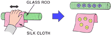
with fur up to the rod A. Take a plastic rod and rub it with fur. Bring
the plastic rod to up to the suspended rod A. Repeat the exercise with
acetate and glass rod rubbed with silk cloth.
Observation
An
electrified polythene rod repels another electrified polythene rod. An
acetate rod rubbed with silk repels another acetate rod rubbed with silk
cloth but it attracts a plastic rod rubbed with fur.
Explanation
Polythene
and plastic when rubbed with fur becomes electrified with the same kind
of electricity known as negative electricity (charge).
Acetate
and glass when rubbed with silk cloth becomes electrified with the same
kind of electricity called positive electricity(charge).
Charging is the process of electrifying a body.
A
positively charged body carries positive charges and a negatively
charged body carries negative charges.The symbols used for positive and
negative charges are + and – respectively.
The Fundamental Law of Static Electricity
State the fundamental law of static electricity
The Fundamental law of electrostatic charges states that:“Like charges repel each other while unlike charges attract each other”
Charging Bodies Using Different Methods
Charge bodies using different methods
In
order to understand the process of charging we have to understand the
structure of bodies or things. All bodies are made up of extremely
small, indestructible bits of matter called atoms.
An
atom consists of a nucleus surrounded by electrons. The nucleus
consists of proton and neutron.The protons are positively charged while
electrons are negatively charged and the neutrons are neutral.
The whole atom is electrically neutral because it contain equal number of protons and electrons.
The following are the methods of charging;
- Rubbing
- Induction
- Contact
Charging by rubbing
A
polythene rod rubbed with fur becomes negatively charged.Rubbing
results in the transfer of electrons from fur to the polythene rod.
Fur
becomes positively charged because some of its electrons are
transferred to the polythene rod.The polythene gains excess electrons
and hence it becomes negatively charged.
Note:It is only the electrons in matter which can be transferred by rubbing.
Charging by induction
A charged polythene rod is held near uncharged copper rod suspended from a cotton thread.
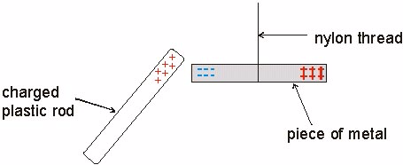
The
electrons of the copper rod are repelled by the negatively charged
polythene rod.Hence the electrons move to the far side of the copper
leaving behind a net positive charge on the side facing the polythene
rod.
Touch
the copper rod with your finger when the charged rod is still in
position. The electrons from copper rod flow through your body to the
earth. Leaving it with a net positive charge. Remove the finger from the
copper rod and finally remove the charged polythene rod.
The
rod has therefore been positively charged by electrostatic
induction.The charges that appear on the copper rod are called induced
charges.
Charging by contact
A charged body (eg; positively charged metal can) is brought in contact with uncharged body B.
Detection of Charges
The Structure of a Gold-leaf Electroscope
Describe the structure of a gold-leaf electroscope
The instrument used to detect the presence of electric charges is called gold leaf electroscope. It consists of an insulated brass rod with two pieces of thin gold foil at one end and a brass cap at the other end.
When
the brass cap is touched with a charged object the leaves of the
electroscope spread out. This is because the charge on the object is
conducted through the brass cap and the brass rod to the leaves.

As they received the same kind of charge, the leaves repel each other and thus spread apart, this is charging by contact.
If
you touch the brass cap with your finger, the charge is transferred
through your body to the earth and the leaves of the electroscope then
collapse together.
Function of an electroscope
- Testing for the sign of the charge on the body.
- Identifying the insulating properties of materials.
- Detecting the presence of charge on a body.
The Sign of Charges
Determine the sign of charges
The
true sign on a body has to be determined before use; the instrument
that can be used to determine the presence of charge is called an
electrophorus.
An
electrophorus consists of a circular slab of insulating material
(polythene) together with a brass disc (conductor) on an insulating
handle.
An
electrophorus works by electrostatic insulation and hence can be used
to generate positive charges from single negative charges. The charge
produced on the insulating slab is negative. The top disc is then placed
on it. Since the surface is only in contact at relatively few points, a
positive charge is induced on the lower surface and corresponding
negative charge is produced on its top surface.

The
top of the upper disc is then touched briefly using a finger, hereby
carrying away the negative charge to the earth; this is called EARTHING.

Steps of Charging and Discharging of a Gold-leaf Electroscope
Identify steps of charging and discharging of a gold-leaf electroscope
The
polythene slab is charged negative by rubbing it with fur. The brass
disc is then placed on top of the slab so that the two charges become
induced onto respective materials.
Note:Contact
does not negatively charge the disc because it is not flat and makes
contact with the slab at a few points only. When the brass disc is
touched with a finger, electrons on the upper surface are repelled to
the earth.
There
is a force of attraction between the metal disc and the base. A spark
(electric energy) is normally produced upon their separation. This spark
can be used for lighting gas burners in laboratory.
The electrophorus can now be used to charge a gold leaf electroscope.

It can be used to charge a gold leaf electroscope by:
- Contact
- Induction
By contact
Here
a positively charged electrophorus is made to touch the brass cap of
the gold-leaf electroscope. The leaf of the gold-leaf electroscope
diverges.
When
a charged electrophorus is brought into contact with the electroscope,
the latter gets charged and the leaves diverge. It acquires a negative
charge. This is determined using the charged rods. When a positively
charged glass rod is brought near the cap. It causes the leaf to
collapse.

By induction
Induction- is the transfer of opposite effects from one body to another without contact.
In
order to obtain a charge of a given sign, the inducing charge must be
of an opposite charge. If charge is placed on an insulator at a given
location the excess charge will remain at the initial location. The
particles of the insulator do not permit the free flow of electrons.
Charge present in an insulator or conductor.

Discharging a gold leaf electroscope
Having charged a gold leaf electroscope by contact and induction, the same can be discharged effectively through induction.
If
while the electroscope is being charged by induction you touch the
brass cap, electrons will leave the electroscope through your hand and
onto the ground. If the charged metal rod is removed, the electroscope
will remain charged. The charge remaining on the electroscope will be
the opposite of the charge on the rod.
If
a negatively charged object is now brought near the brass cap electrons
in the brass cap are repelled and moved down to the leaves. This
cancels the positive charge. With no net charge, the leave collapse back
together.
If
the object is removed, the electrons return to the metal cap leaving
the leaves of the electroscope with a net positive charge again and they
separate.

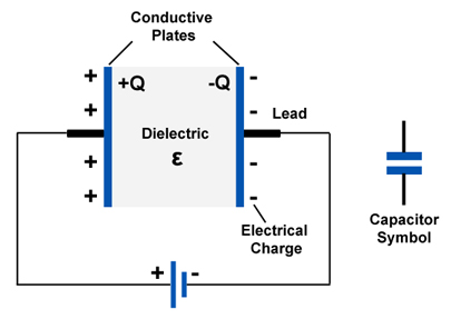
Capacitors
Capacitor
is a device which is used for the storage of charges consisting of two
conductors, parallel-nearly separated by air or any other dielectric.Dielectric is an insulating medium used between plates of a capacitor.
Mode of Action of a Capacitance
Explain mode of action of a capacitance
Consider
two unequal metal cans which were made to stand on the caps of two
identical electroscopes.These cans are given equal charges of Q units
from an electrophorus disc. The charged disc is lowered inside a can
until it touches the bottom. In this way the whole of the charge is
given up to the can and goes to the outside.
It
will be noticed that the leaf divergence is greater for the small can,
showing that it has acquired higher potential than the larger can.In
this case, the larger can is said to have a larger capacitance while the
smaller can has a lower capacitance.When the two cans are joined by a
wire electricity flows from the smaller can to the larger can until
potentials are equalized.
The Action of a Capacitor
Explain the action of a capacitor
The
positive charge on A induces an equal and opposite charges on opposite
sides of B. These induced charges will respectively raise and lower the
potential of all points in their neighborhood and in particular they
will affect the potential of plate A.
As
far as A is connected , however the negative induced charge will have
the greater effect. The net result is is that the potential of A is
slightly reduced.
B
is next earthed either by touching it with a finger or by connecting it
to the nearest cold-water pipe. Immediately the leaf shows a great
decrease in divergence. This implies a big decrease in potential, and
hence a big increase in capacitance of A.The presence of the earthed
plate B results in a very large increase in the capacitance of A.
Construction of an Air-filled Capacitor
Describe the construction of an air-filled capacitor
This
constitute two parallel metal plates with air band between them.A flat
metal A is set up vertically on insulating legs and is connected to a
gold leaf electroscope by means of a wire.
The
plate is then given a positive charge by induction with a negatively
charged ebonite rod. The divergence of the leaf indicates the potential
of the plate.A second insulated plate B is now brought up slowly into a
position parallel to A.
When
B is very close to A but not touching it, it will be noticed that the
leaf divergence decreases very slightly.We conclude from this that the
potential of A has been decreased by the presence of B, and hence its
capacitance has increased slightly.
Equivalence Capacitance of a Combination of Capacitors
Determine equivalence capacitance of a combination of capacitors
Factors affecting the capacitance of a parallel-plate capacitor.
There are three factors which affect the capacitance of a parallel-plate capacitor, namely;
- Area of plates
- Distance apart of the plates.
- Dielectric between the plates.
Relative permeability (dielectric constant) of a medium
Relative permeability
is the ratio of the capacitance of a given capacitor with the medium as
dielectric to the capacitance of the capacitor with a vacuum as the
dielectric.
It
has no units since it is a ration of similar quantities.Paraffin wax
has a relative permeability of about 2 while that of mica is about 8.
Charge Distribution Along the Surface of a Conductor
Charge on a Conductor Reside on its Outer Surface
Recognise that charge on a conductor reside on its outer surface
Usually, charges are distributed on the outer surface of conductors of different shapes.
Investigating surface distribution of a charge on conductors
- A proof plane is pressed into contact with the surface at various places of the conductor.
- The charges on the proof plane are then transferred to the electroscope.
- The divergence of the leaf will give a rough measure of the amount of charge transferred and hence surface density of the charge.
Charge on a Conductor is Concentrated on Sharply Curved Surfaces
Show that charge on a conductor is concentrated on sharply curved surfaces
So
far we have considered excess charges on a smooth, symmetrical
conductor surface. What happens if a conductor has sharp corners or is
pointed? Excess charges on a nonuniform conductor become concentrated at
the sharpest points. Additionally, excess charge may move on or off the
conductor at the sharpest points.
To
see how and why this happens, consider the charged conductor. The
electrostatic repulsion of like charges is most effective in moving them
apart on the flattest surface, and so they become least concentrated
there. This is because the forces between identical pairs of charges at
either end of the conductor are identical, but the components of the
forces parallel to the surfaces are different. The component parallel to
the surface is greatest on the flattest surface and, hence, more
effective in moving the charge.
The
same effect is produced on a conductor by an externally applied
electric field, as seen inFigure(c). Since the field lines must be
perpendicular to the surface, more of them are concentrated on the most
curved parts.
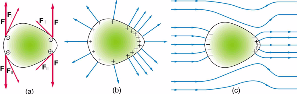
Excess
charge on a nonuniform conductor becomes most concentrated at the
location of greatest curvature. (a) The forces between identical pairs
of charges at either end of the conductor are identical, but the
components of the forces parallel to the surface are different. It
isF∥that moves the charges apart once they have reached the surface.
(b)F∥is smallest at the more pointed end, the charges are left closer
together, producing the electric field shown. (c) An uncharged conductor
in an originally uniform electric field is polarized, with the most
concentrated charge at its most pointed end.
Lightning Conductor
The Phenomenon of Lightning Conductor
Explain the phenomenon of lightning conductor
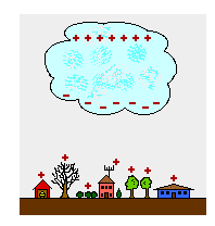
Lightning is a gigantic electric spark discharge occurring between two charged clouds or between a cloud and the earth.
Ligthning conductor
is a long pointed iron rod with its lower end buried in the earth and
the other above the highest part of the building which is used to
protect the building from lightning damage.
The Structure and Mode of Action of Lightning Conductor
Describe the structure and mode of action of lightning conductor
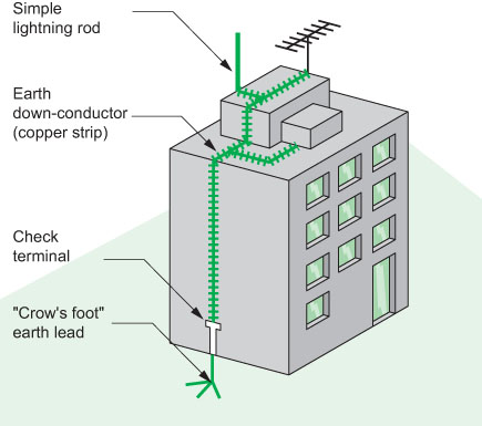
Structure of a lightning conductor
It
consists of a long thick pointed copper rod with its lower end buried
in the earth(earth plate) and the other end reaching above the highest
part of the building and ending in several sharp spikes. -It is fixed to
the side of the building.
Mode of action of lightning conductor
When
a negatively charged thunder-cloudpasses overhead it acts inductively
on the conductor,charging the points positively and the earth plate
negatively.
The
negative charge on the plate is, of course, immediately dissipated into
the surrounding earth. At the same time point action occurs at the
spikes. Negative ions are attracted to the spikes and becomes discharged
by giving up their electrons. These electrons then pass down the
conductor and escape to earth.
At
the same time positive ions are repelled upwards from the spikes and
spread out to form what is called a space charge. This positive space
charge, however, has a negligible effect in neutralizing the negative
charge on the cloud.
Note:Without
the protection of a lightning conductor the lightning usually strikes
the highest point, generally a chimney, and the current passes to earth
through the path of least resistance. Considerable heat is generated by
the passage of the current and sometimes it may set into fire.
A Simple Lighting Conductor
Construct a simple lightning conductor
A simple lightning conductor
TOPIC 2: CURRENT ELECTRICITY
Electric
current is the rate of charge flow past a given point in an electric
circuit, measured in Coulombs/second which is named Amperes. In most DC
electric circuits, it can be assumed that the resistance to current flow
is a constant so that the current in the circuit is related to voltage
and resistance by Ohm's law. The standard abbreviations for the units
are 1 A = 1C/s.
Simple Electric Circuits
Simple Circuit Components
Identify simple circuit components
An
electric circuit contains a source of moving charge (battery or
generator), connecting wires made of conducting materials (usually
copper metal) and various electrical devices such as bulbs, switches,
resistors, ammeters and voltmeters.
Voltmeters
measure potential difference in volts. While resisters opposes the flow
of current. The circuit may also contain devices for controlling the
amount of current. These include:
- Rheostat
- Fuse
- Circuit breakers, as well as devices for measuring current such as ammeters and galvanometers.
The table below shows list of some common circuit component and their purpose.
| Circuit device | Purpose |
| Connecting wire | Carry current from point to point in a circuit. |
| Wire joined | |
| Wire crossing (can be connected) | |
| Cell | Supplies electrical energy |
| Battery (4 cells) | Supplies electrical energy |
| Battery (multiple cells) | |
| Alternating current (AC) supply | |
| Lamp/bulb | Supplies electrical energy |
| Resistor | Impedes the flow of current |
| Switch | Open and closes a circuit |
| Rheostats (variable resistors | Control amount of current. For example the brightness of a lamp) |
| Galvanometer | Detecting the presence of current |
| Ammeter | Measures current |
| Milliammeter | |
| Voltmeter | Measures potential Difference (voltage) |
| Capacitor | Store charges |
Simple Electric Symbols
Identify simple electric symbols
Connecting wire

Wire joined

Wires crossing

Cell

Battery

Battery (multiple cells)

Alternating current (AC) supply

Lamp/bulb

Resistor

Switch

Rheostats (variable resistors)

Galvanometer

Ammeter

Milliammeter

Voltmeter

Capacitor

Potential Difference (P.D)
Potential difference or voltage is a measure of electrical energy.
Potential
difference (p.d) between the +ve and –ve terminals of a battery causes a
current to flow along any conducting path that links them.

The Concept of Current, Voltage and Resistance
Explain the concept of Current, Voltage and Resistance
CURRENT
An
electric current in a material is the passage of charge through the
material. In metals free electrons carry charge. In solutions such as
sodium chloride it is carried by charged particles known as ions.
Insulators
like wood and plastic do not contain charge carriers at all as every
electron is firmly fixed onto their atoms. The electrons are not free to
move.
The
rate of flow of electrons in a material is called electric current. It
is measured in amperes (A) using an Ammeter. Connection can damage them.
Therefore when connecting the ammeter, the red wire should be connected
to the +ve terminal of a battery.
A current of 1A is equivalent to a flow of6.25 x 1018electrons per second and 1 electron has a charge of 1.6x 10⁻¹⁹c.
Current in simple circuit is the same at all points.
Once
the circuit is complete, electric charges inside cells and other
sources of electric charge are forced out into the circuit.
The
electric energy is normally given out as light and heat, as energy goes
through the bulb. A car headlamp has about 4A of current passing
through it while a small torch uses about 0.2A.
VOLTAGE
When
several cells have been joined together, they form a battery. Every
cell has a voltage, commonly referred to as potential difference (p.d).
This potential difference (p.d) causes the flow of electrons (charges)
in a circuit.E.g. A dry cell has a voltage of 1.5v. This voltage is
normally marked on the cell.
Voltage
is measured by using a voltmeter. The SI unit for voltage is the volt
(V). If each coulomb if charge is given 1 joule of potential energy,
then the p.d across the terminals of a battery is 1 volt.
The p.d between the ends of a connecting wire is zero since there is almost no loss of potential energy over this section.
P.d
across the battery = sum of p.d around a conducting path, whereas
voltage provides the driving force to an electric current, this force is
always opposed.
RESISTANCE
Is
the opposition flow to an electric current. As current flows through
the circuit it encounters some opposing force. This force determines the
amount of current flowing in an electric device.
The
property of conductors that oppose the flow of electric charges depends
on the relationship between current and voltage across their ends as
discovered by George Ohm. He observed that voltage across a conductor
was directly proportional to electric current flowing through it
provided that temperature and other physical conditions of the conductor
were kept constant.
Hence, V x I
V= IR
R is the constant of proportionality. This constant is called resistance and the above relationship is known as Ohms law.
Resistant (R) = p.d across the conductor/Current through the conductor
Therefore a resistance of 1ohm is obtained when a p.d of 11V cause a current of 1A to flow in a circuit.
| name | symbol | conversion | example |
| milli-ohm | mΩ | 1mΩ = 10-3Ω | R0 = 10mΩ |
| ohm | Ω | - | R1 = 10Ω |
| kilo-ohm | kΩ | 1kΩ = 103Ω | R2 = 2kΩ |
| mega-ohm | MΩ | 1MΩ = 106Ω | R3 = 5MΩ |
A resistor
Is
a device especially designed to offer resistance to the flow of an
electric current, Resistors include rheostats (variable resistor) and
fixed resistors.
Ohm's Law
Ohms
law states, “At constant temperature and other physical factors, the
potential difference across the end is directly proportional to the
current passing through a conductor (wire).”
A graphical representation of Ohm's law. The graph of voltage against current

The
gradient of the particular graph represents resistance. This is
constant for a particular wire or conductors. Doubling the voltage would
double the current; a graph of this kind passes through the origin.
FACTORS THAT AFFECT THE RESISTANCE OF A CONDUCTOR
The resistance of a conductor is affected by the following factors:
Length of the conductor
The
longer the wire, the higher the resistance, short lengths of wire
produce resistors of low resistance while long lengths of the same wire
are good for high – value resistance.
Temperature
An
increase in temperature of a conductor means an increase in its
resistance and vice versa. This is important in resistance thermometers.
The resistance of metal conductor increases with increase in
temperature.
Types of material
The
conducting ability of the material has to be considered. A chrome wire
has more resistance than a copper wire of the same dimension. That is
why copper is mostly used for connecting wire.
Cross – sectional area
A
thin wire has more resistance than a thick conductor. The filament of a
bulb is made of very thin tang stem wire. It therefore has a high
melting point.
With
all other factors being equal, a long wire has more resistance than a
short wire and thin wire has more resistance than a thick one. Therefore
resistance of a conductor varies depending on the current flow.
The SI Units of Current, Voltage and Resistance
State the SI units of Current, Voltage and Resistance
Current
The
rate of flow of electrons in a material is called electric current. It
is measured in amperes (A) using an Ammeter. The SI unit for current is
ampere.
Voltage
Voltage is measured by using a voltmeter. The SI unit for voltage is the volt (V)
Resistance
Resistant (R) = p.d across the conductor/Current through the conductor. The SI unit for resistance is Ohm.
Connecting Simple Electric Circuits
Connect simple electric circuits
CONSTRUCTION OF SIMPLE ELECTRIC CIRCUITS
Consider a circuit consisting of a battery, a switch and 2 bulbs.
When
the switch is closed, current flows through the wires and the bulbs
light up. The circuit is said to be complete. When the switch is opened,
no current flows through the wire, as the path carrying current is
broken. The circuit is said to be incomplete.

If we want to be able to control the brightness of the lamp, we include a rheostat into the circuit.
In
a circuit an ammeter is always connected in series with the battery.
Current has to pass through the ammeter if it is to be measured
correctly.

Unlike
an ammeter, a voltmeter must be connected in parallel with component so
as to measure the voltage drop across it. The figures show a simple
electric circuit in which the ammeter and voltmeter are connected in
series and parallel respectively.
As
already learnt, resistance is the ratio of the potential difference
across the ends of the conductor,a very good conductor will have 0
resistance.

Resistance of resistor R could be calculated using the formula:- R = V/I
R = V/I
Not that the rheostat (variable resistor) moves, it varies with the length of the conductor being used.
Example 1
A battery of 5V has a resistance wire of 20Ω connected to it. Calculate the current in the circuit.
Solution;
I = V/R = 5V/20Ω
I = 0.25A
Therefore,
Current in the circuit = 0.25A
Example 2
Calculate the reading of the Voltmeter P and the ammeter Q in the electric circuit below.
Solution:

Being a single loop circuit, current is the same at all points.
Q = 3A
Sum of p.d in external circuit = p.d across battery
3V + P = 13V
P = 10V
Therefore:
Q = 3A and Voltmeter P = 10V
Note: for a single loop or simple circuit.
- Current is the same at all points around the circuit
- The sum of the potential differences around a conducting path from one battery terminal to the other terminal within the circuit is the same as the p.d across the battery.
Electric Current and Voltage
Measure electric current and voltage
MEASUREMENT OF ELECTRIC CURRENT
Since we cannot see electric current to measure it, we must observe some of its visible effects, like deflection of pointers.
Beside
an ammeter, an electric current is measured using Milliammeter and
microammeters. These devices are normally connected in series with the
source of current e.g. circuit with a galvanometer connected in series.

Galvanometer in series
Galvanometer
can only measure very small current of a few hundred microamperes. To
measure large currents a resistor is added to make current flow through
it and a very small amount of current flows to the galvanometer. This
combination is called an ammeter.
On
the other hand voltage is measured depending on the amount of current
passing through the circuit. In Ohmic device it is given as V^I.
Simple Electric Circuits
Analyse simple electric circuits
Combination of resistors
There
are two main methods of connecting circuit components, in series or in
parallel. Resistors can be connected either in series or in parallel
depending on the desired output.
Series combination
In series arrangement the resistors are connected end to end.
In a simple circuit
V = V1 + V2 or V- (V1 + v2)= 0
This means that the sum of the p.d across the resistors is the same as the p.d across the battery.
Current is the same at all points around the circuit.
Resistors connected in series

Parallel combination
Resistors are connected across two common points in a parallel arrangement.
Note;
Potential difference is from a single source and so is the same for all
the branches. However the current is different in each branch.

From Ohm's law;
Note:

When
bulbs have to be powered by a single source of electric current, the
bulbs are connected in parallel. This is practiced in car and home
lighting system.
The advantage of parallel arrangement over series arrangement is that:
- The full p.d of source is applied across each bulb irrespective of the number of bulbs.
- Switching one bulb on and off does not affect the others.
Example 3
consider the figure below:
Given that the p.d a cross the cell is 24V, calculate the p.d across the 4Ω and 6Ω.

Solution;
Total resistance in the circuit = 4Ω + 6Ω= 10Ω
Using Ohm’s law. I = V/R,
Current in the circuit = 24V/10Ω= 2.4A
This implies the 2.4A passed through the 4Ω resistor.
The pd across it can be obtained through V=IR
p.d = 2.4A x 4N = 9.6V
Note that the p.d across two resistors adds up to the battery p.d.
p.d across the 6Ω = (24-9.6) V
= 14.4V
Therefore,
P.d across the 6Ω =14.4V
ALL TOPICS FOR PHYSICS FORM TWO
PHYSICS TOPIC 1-2.
PHYSICS TOPIC 3-4.
PHYSICS TOPIC 5: SIMPLE MACHINES
PHYSICS TOPIC 6: MOTION IN STRAIGHT LINE.
PHYSICS TOPIC 7 & 8:
PHYSICS TOPIC 9: SUSTAINABLE ENERGY RESOURCE
O'LEVEL PHYSICS
PHYSICS FORM FOUR
PHYSICS FORM THREE
PHYSICS FORM TWO
PHYSICS FORM ONE


No comments